SynTemp® – Temperature Monitoring SynTemp® S01/S02 or S06/S08
Series S01 or S06 thermal cut-offs are moulded, permanently operating bimetal release switches which interrupt the current flow once the nominal temperature has been reached (normally closed contact). Closing combination also possible (S02 or S08).
Permanent operation with immediate reaction once the switching temperature has been reached is ensured due to the unique free-moving and self-aligning construction of the bimetal disc in the thermal cut-off. The thermal cut-offs are available as a single component and in a twin or triplet version.
Further advantages due to the bimetal perforated discs:
- excellent long-term stability
- improved space utilisation
- high mechanical strength
- excellent long-term stability
Application
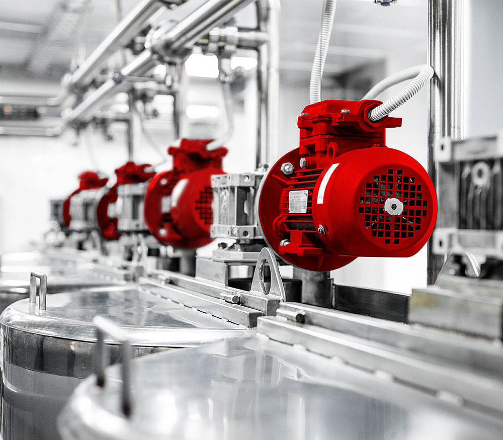
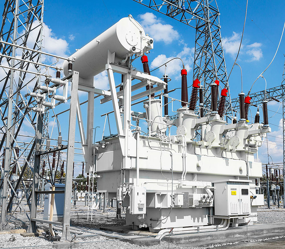
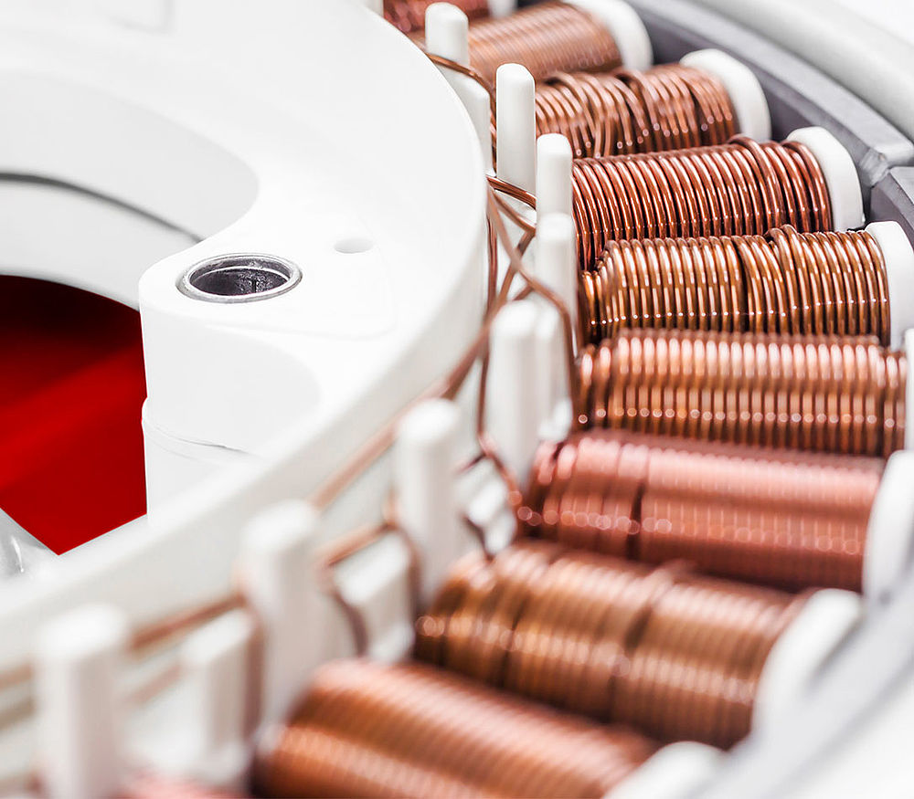
The S01 and S06 thermal cut-offs are used in electric motors and transformers.
Standards
VDE EN 60 730-2-9,
UL/CSA 2111, File Nr. E54236
ENEC acc. to EN 60730
Delivery forms
Nominal switching temperature in 5°C-steps of 60 to 200°C as standard, further temperatures on request.
Version: 01 available with (S01) or without (C01) insulation cap out of Mylar® / Nomex®, Epoxy resin impregnated or bare.
Version: 06 available with (S06) or without (C06) insulation cap, basically Epoxy resin impregnated.
Standard cable length 300 mm, other lengths on request.
Technical data
| Property | Unit of measure | S01 | S02 | S06 | S08 |
|---|---|---|---|---|---|
| Switch type | Opening contact | Closing contact | Opening contact | Closing contact | |
| Nominal switching temperatures | °C | 60-200 | 60-200 | 70-200 | 70-180 |
| Tolerance | K | ±2.5 / ±5 | ±5 | ±5 | ±5 |
| Reverse switch temperature | Depending on NST | Depending on NST | Depending on NST | Depending on NST | |
| Total bouncing time | ms | <1 | <1 | <1 | <1 |
| Operating voltage AC/DC | V | up to 500 AC / 14 DC | up to 500 AC | up to 500 AC/28 DC | up to 500 AC |
| Rated voltage AC | V | 250 (VDE)/277 (UL) | 250 (VDE)/277 (UL) | 250 (VDE)/277 (UL) | 250 (VDE)/277 (UL) |
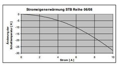
| Rated current AC cos φ=0,4 | A | 1.8 / 10,000 cycles | no specification | no specification | no specification |
| Rated current AC cos φ=0.6 | A | 1.6 / 10,000 cycles | 1.6 / 10,000 cycles | 6.3 / 10,000 cycles | 6.3 / 10,000 cycles |
| Rated current AC cos φ=1.0 | A | 2.5 / 10,000 cycles | 2.5 / 10,000 cycles | 10.0 / 10,000 cycles | 10.0 / 10,000 cycles |
| Max. switching current AC cos φ=0.4 | A | 7.2 / 1,000 cycles | no specification | no specification | no specification |
| Max. switching current AC cos φ=1.0 | A | 6.3 / 3,000 cycles; 7.5 / 300 cycles | no specification | 25.0 / 100 cycles | no specification |
| Property | Unit of measure | S01 | S02 | S06 | S08 |
|---|---|---|---|---|---|
| Contact resistance | mΩ | ≤50 | ≤50 | ≤50 | ≤50 |
| High-voltage resistance | kV | 2.0 | 2.0 | 2.0 | 2.0 |
| Standard connection lead wire | mm² | 0.25 / AWG22 | 0.25 /AWG22 | 0.75 / AWG18 | 0.75 / AWG18 |
| For devices in protection class | I+II | I+II | I+II | I+II | |
| Diameter (with/without insulation cap) | mm | 9.5 | 9.5 | 10.5 | 10.5 |
| Installation height of the housing (with/without insulation cap) | mm | from 4.3 | from 4.7 | from 7.0 | from 7.0 |
| Length of insulation cap | mm | 15.0 | 15.0 | 17.5 | 17.0 |
| Pressure resistance of the housing | N | 450 | 450 | 600 | 600 |
